BACKGROUND OF THE INVENTION
The present invention
relates to hydraulic power generation systems and, in particular, to an apparatus
and method for generating power using a novel pseudo-osmosis process which
efficiently exploits the osmotic energy potential between two bodies of water
having different salinity concentrations.
SUMMARY OF THE INVENTION
Accordingly, it is an
aspect to provide an improved apparatus and method for generating power using
a novel forward osmosis process which efficiently exploits the osmotic energy
potential between two bodies of water having different salinity concentrations.
Advantageously, the method
and apparatus of the present invention does not necessarily require the use
of (but may use) a semi-permeable membrane or other specially formulated material,
nor does it require heating or cooling of the fresh water or salt water solution.
Moreover, the present invention may recover energy from a wide variety of
fresh water sources, including treated or untreated river run-off, treated
waste-water run-off or effluent, storm-drain run-off, partly contaminated
fresh water run-off, and a wide variety of other fresh water sources. Thus,
the present invention may be well suited, in one possible embodiment, to large
scale power production in a wide variety of geographic locations and under
a wide variety of conditions. The invention has particular advantage for use
in remote regions where electrical power generation by conventional means
may be commercially infeasible or impractical.
According to one aspect
of the invention, there is provided a mixing apparatus for mixing first salinity
fluid with a second salinity fluid, the mixing apparatus comprising: a tube
having a side wall, an open upper end and an open lower end, and a plurality
of apertures selectively located in the side wall of the down tube; a fluid
inlet and a fluid outlet at the open upper end and open lower end respectively
of the tube, wherein the first salinity fluid in use enters the tube through
the fluid inlet and is discharged therefrom through the fluid outlet; and
a surrounding reservoir having a second salinity fluid having a salinity different
to the first salinity fluid.
According to yet another
aspect of the invention, there is provided a mixing apparatus for mixing first
salinity fluid with a second salinity fluid, the mixing apparatus comprising:
a tube through which the first salinity fluid flows, the tube having a side
wall and an open upper end and an open lower end, the tube having a porous
screen tube, the tube being located in a container or tank which has flowing
therethrough the second salinity fluid.
In yet another aspect
of the invention, there is provided a mixing
apparatus for mixing first salinity fluid with second salinity fluid, the
mixing apparatus comprising: a down tube having a side wall and an open upper
end and an open lower end, the side wall being comprised of a meshed screen
portion and solid portion below the meshed screen portion; a fluid inlet and
a fluid outlet at the open upper end and open lower end respectively of the
down tube, wherein the first salinity fluid in use enters the down tube through
the fluid inlet and meshed screen portion and is discharged therefrom through
the fluid outlet; a feed tube having a first end connectable to a source of
second salinity fluid having a salinity different to the first salinity fluid
and a second end for introducing second salinity fluid to the fluid inlet
of the down tube to mix the first salinity fluid with the second salinity
fluid to form a fluid mixture.
BRIEF DESCRIPTION OF THE DRAWINGS
Figures 1(a) and 1(b)
show schematic views of an osmosis apparatus and process which is typical
of the prior art; and
Figure 2 is a schematic
view of a hydrocratic generator in accordance with one aspect of the present
invention.
Figures 1(a) and 1(b)
DESCRIPTION OF THE PREFERRED EMBODIMENTS
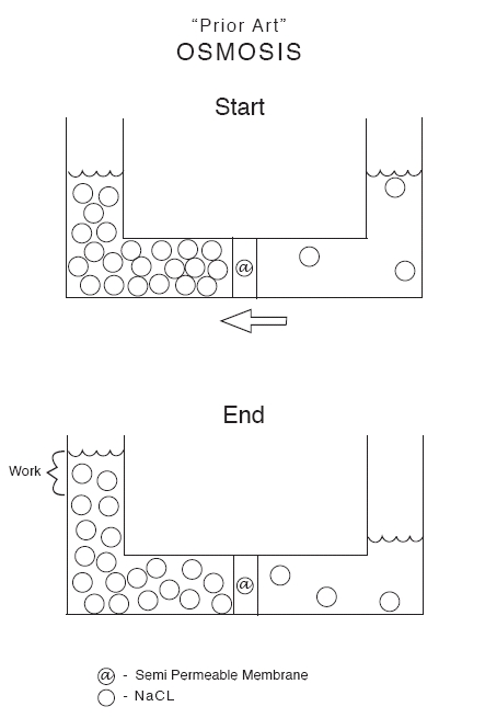
In Figures 1(a) and 1(b)
of the drawings, there is shown a prior art apparatus and procedure for osmosis.
Figure 1(a) shows the apparatus at the start position while Figure 1(b) shown
the apparatus at the end position. The osmosis device 10 comprises trough
12 having a base portion 14 and a pair of lateral upright portions 16 and
18. A fluid 20 including NaCl is placed in the device. The base portion 14
has about midway along its length a semi-permeable membrane 22 through which
osmotic flow of the liquid, which is water, will flow.
In Figure 1(a) of the
drawings, the start position, it will be seen that the level 26 in the upright
portion 16 is substantially the same as the level 28 in the upright portion
18. As the process of osmosis progresses, with diffusion across the SMP 22,
the level 26 rises and the level 28 drops in the upright portions 16 and 18
respectively. These figures illustrate the typical osmotic effect, which is
able to release energy.
Reference is now made to Figure 2 of the drawings showing one aspect
of the present invention.
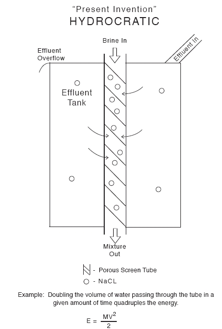
Figure 2 of the drawings
shows a hydrocratic generator 40, a device which is capable of using two liquids
each having a different water potential to generate power or do some selected
work requiring energy input. The hydrocratic generator 40 comprises a reservoir
or effluent tank 42 which comprises a base 44 and side walls 46 which together
define a space 48. The tank 42 has an inlet 50 through which effluent or other
water type is introduced into the tank 42. The effluent fills the tank 42
and may eventually overflow when the tank 42 is full through an outlet or
over the rim 52. There is thus a constant flow of effluent working its way
through the tank 42.
A pipe or tube 56 is
passes through the tank 42 as shown in the Figure 2 of the drawings. The tube
56 has an upper end 58 and a lower end 60, both of these ends extending beyond
the periphery or limits of the tank 42. The tube is comprises at least in
part of a porous screen 62 which allows for diffusion of liquid between the
liquid in the space 48 and liquid flowing through the interior 62 of the tube
56.
Brine flows from the
upper end 58 of the tube 56, through the interior 64 of the tube 56 and out
through the lower end 60. As brine flows through the tube 56 and effluent
flows through the tank 42, the porous screen 62 allows for the necessary exchanges
and interactions between the effluent and the brine and the different osmotic
potentials between these liquids is exploited to harness power or energy.
The power or energy may be used or stored in various manners which will not
be specifically described herein. However, there are many different mechanisms
for using or storing this energy and any one or more of these falls within
the scope of the present invention.
The volume of flow through
the tube can be selected varied over a given period of time. The volume flow
affects the energy produced. In one example, doubling the volume of water
passing through the tube on a given amount of time can quadruple the amount
of energy produced. It is believed that the energy produced will be in accordance
with the following formula:
MV2
E =
2
In a pipe with a fixed
diameter that is filled with a liquid, if the quantity of liquid flowing through
that pipe is increased, the velocity of the liquid increases. The square of
this increase is the increase in the Kinetic Energy of the liquid.
The invention covers
the use of different tank shapes, or even surrounding ambient water, and different
tubes which may be configured and selected to optimize the flow and energy
generated in a given situation, given the different types of water and their
differing water potentials.
When solvent fluids having
differing osmotic potentials are contacted and mixed with each other energy
is released. This released energy results from an increase in entropy of water
(or other solvent) when it is transformed from its pure (fresh-water) state
to its diluted (salt-water) state. Thus, an entropy gradient is created whenever
two bodies of water or other solvents having differing solute concentrations
are brought into contact with one another and begin to mix. This entropy gradient
can be physically observed and measured in the well-known phenomena known
as osmosis.
Because the term “osmosis”
is associated with a membrane, the term “hydrocrasis” is used as a term for
the situation when solvent fluids having differing osmotic potentials are
contacted and mixed with each other in the absence of a membrane.
During testing of an
upwelling device it was discovered that the amount of upwelling flow achieved
in terms of kinetic energy of the overall mass flow was in excess of the input
energy into the system in terms of the buoyancy effect and kinetic energy
resulting from the water introduced into the tube. Subsequent experiments
using a modified upwelling device have confirmed that the total hydraulic
energy output of such system significantly exceeds the total hydraulic energy
input.
In one possible embodiment,
fresh water is introduced into the tube in order to power the device. The
term “fresh” water as used herein is to be interpreted in a broad sense as
water having an osmotic potential relative to sea water. Thus, it may be used
to describe the input stream a river discharge, a mountain run-off, a treated
sewage discharge, a melting iceberg, or even runoff from a city storm drainage
system.
The fresh-water input
stream may be conducted though the tube by applying pressure at the inlet
end of the tube. The pressure may be provided by a pumping station or with
a hydrostatic head pressure resulting from a fluid reservoir at a higher elevation.
The pressure applied at the inlet end of the tube need only be high enough
to overcome the hydrostatic head at the outlet end of the tube.
It has been found that,
when fresh water is introduced into a down tube, sea water flows into the
up tube, causing upwelling in the up tube that can be used to generate power
with the power generator. Some of this upwelling effect is due to the increased
buoyancy of the mixed water in the up tube, because fresh water has a lower
density than sea water. However, far more upwelling of sea water is observed
than would be expected from this phenomenon alone. It is believed that the
apparatus and the method is able to harness the energy available from the
different osmotic potentials of fresh water and sea water. The amount of upwelling
and the amount of power that is generated in the device depend in part on
the particular dimensions of the tube and the flow rate of fresh water in
the down tube.
In operation in accordance
with one aspect of the invention, fresh water exiting the down pipe through
the radial apertures is mixed with water of higher salinity. The energy produced
by the mixing of the water of higher salinity and lower salinity drives turbines.
Other Applications/Embodiments
In the preferred embodiments
discussed above, the tube is located in a body of water of high salinity and
high negative osmotic potential such as an ocean or a sea.
Alternatively, the invention
can be operated between bodies of salt water having different salinity or
between waters at different depths of the same body of water. For example,
the salinity and temperature of sea water is known to vary with depth and
location.
While the present invention
is disclosed, in one embodiment only, in the context of generating power by
directly contacting and mixing fresh water with sea water in an apparatus
located in the ocean, it is to be understood that the apparatus and method
are not limited to this embodiment. The techniques and concepts taught herein
are also applicable to a variety of other situations where aqueous solutions
having differing osmotic potentials are available. For example, in one embodiment,
the apparatus and method may be applied to a concentrated brine from a desalinization
plant being mixed with the less-concentrated brine in sea water. In another
embodiment, a treated sewage effluent, a fresh water stream, can be mixed
with sea water. If desired, an osmotic membrane or osmotic water exchange
plenum may be provided at the outlet end of a down tube and/or at the outlet
(top) of the up tube in order to increase the efficiency of energy production.
The apparatus and method may thus be applied to a wide range of applications
in which two solutions of differing osmotic potential are available.
The various embodiments
of the invention disclosed and described herein are exemplary only. As such,
these example embodiments are not intended to be exhaustive of all possible
ways of carrying out the invention or even the most economical or cost-efficient
ways of carrying out the invention on a commercial scale. Accordingly, it
is intended that the scope of the present invention herein disclosed should
not be limited by the particular disclosed embodiments described above, but
should be determined only by a fair reading of the claims that follow.
wader1147-123.US02